Detallado experimento Worksharing a través de internet, 1ª parte: Introducción y conclusiones | BIMlevel.com http://ow.ly/rFIAj
Detallado experimento Worksharing a trav
Reply

Detallado experimento Worksharing a través de internet, 1ª parte: Introducción y conclusiones | BIMlevel.com http://ow.ly/rFIAj
Magnificent simplicity with a little joke by Johnny Osborne http://ow.ly/qzW2P Certainly, I love it.
Reblog del artículo de investigación sobre aplicaciones BIM para Facilities Management (integrada dentro del Facility Management), publicado en su blog por David Barco Moreno. A mi juicio es un trabajo muy completo de recopilación, siempre útil a la hora de hacer consultas y encontrar información más amplia.
A la espera de información más detallada.
Revit | Building Design and Construction | Autodesk.


© Kris Weeks
Recomiendo la lectura de esta visión de BIM y su desarrollo.
© Kris Weeks
http://www.architecturalevangelist.com/building-information-modeling/braving-the-new-world-of-bim.html
Por el obvio interés que tiene para los usuarios de Revit, me hago eco de la novedad más interesante que presenta Presto 2013, que incorpora un módulo para Revit. Los usuarios de Allplan también dispondrán de un módulo compatible con la aplicación BIM de Nemetschek.
De la Webinar en la que Fernando Valderrama, Director de Soft, presenta las novedades de la versión 2013 de Presto, he extraido los 2 apartados relacionados con el funcionamiento con Revit.
Aquí los dejo:
Aquí dejo un breve tutorial de como girar una vista en Revit, algo poco intuitivo, a juzgar por las dudas que me he encontrado frecuentemente.
One of my tasks in the company I work for, is to give support to other users of Revit, and the most frequently question is, of course: I’ve just placed this element and can not see it. Where is it? , or: How on earth can I see this as I want to! But before they ask me, they have usually spent a long time looking for it unsuccessfully, and usually come to me with a criminal mind that, at the begining is not against me, but they would be able to change if I didn’t solve it quickly.
In the interest of protecting my security, I have been developing during my quiet nights (it’s time that I dedicate to this blog) a guide of how to deal with Revit visibility issues.
My starting point was this post at Revit Forum. Here is a list of possible reasons why an item is not displayed in a particular view. I’ve enlarged it with more cases, some derivative of others, grouped and detailed them with the approach of making it accessible for users with very different levels.
I hope you find it of interest as much as it reassures me :-)
You could also check out this link from Autodesk WikiHelp and look into there what you need.
Una de mis tareas en la empresa para la que trabajo, es la de dar apoyo al resto de usuarios de Revit, y entre las consultas más frecuentes está, cómo no: acabo de colocar este elemento y no lo veo ¿dónde está? ;o bien: ¡Cómo demonios se hace para ver esto como yo quiero! Pero antes de preguntarme, muchas veces ya le han dedicado un largo rato a buscarlo infructuosamente, y suelen acudir con cierto ánimo criminal, que al principio no es contra mí, pero después puede cambiar si no lo resuelvo rápido.
Con el interés de salvaguardar mi integridad, he estado preparando durante mis noches de tranquilidad (es el momento que le dedico a este blog) un guión de cómo actuar ante los problemas de visualización con Revit.
Mi punto de partida ha sido esta entrada del Revit Forum. En ella, hay una lista de posibles motivos por los que no se visualiza un elemento en una vista determinada. La he ampliado con más casos, algunos derivados de otros, agrupado y detallado con el criterio de hacerlo accesible para usuarios de muy distintos niveles.
Espero que os resulte de interés tanto como a mi me tranquiliza:-)
También puedes visitar este enlace de Autodesk WikiHelp y buscar allí lo que necesitas.

Consider whether it is possible to get the desired result in less time by duplicating another existing view, applying a view template already prepared or in any other way, after making the necessary changes, which can lead to find out the reason why an element or category is not displayed.
It is very helpful to use schedules to locate elements not found in model views, using right click > Show … or from the Ribbon with Highlight in Model.
Another option for families is to go to Project Browser, select the family there, and then with right-click choose Select All Instances> In Entire Project. It gives you a clue if you don’t have many identical elements.
Well, good luck.
Considera si es posible en menos tiempo obtener el resultado deseado mediante el duplicado de otra vista existente, aplicando una plantilla de vista ya preparada o por cualquier otro medio, haciendo después las modificaciones necesarias, del que puede llevar averiguar la razón por la que no vemos un elemento o categoría.
Es muy útil recurrir a tablas de planificación para localizar elementos que no encontramos en las vistas de modelo, ayudándonos del botón derecho >Show… o bien desde la Cinta de opciones con Highlight in Model.
Otra opción en el caso de familias, es la de acudir al Buscador de Proyecto, seleccionar allí la familia, y después de pulsar el botón derecho elegimos Select All Instances>In Entire Project. Nos dará una pista si es que no tenemos muchos elementos iguales.
En fin, suerte.
1. Go to VV (Visibility / Graphics Overrides) and verify that the element category or subcategory is not turned off for that view.
2. Go to Reveal Hidden Elements (RH) (bulb on the View Control Bar) and check that the item is not turned off.
3. Check that it isn’t temporarily turning off, turning on all elements, typing (HR) (Temporary / Hide Isolate) or on glasses of View Control Bar. If the view doesn’t have the blue frame, there is no element or category temporarily hidden.
4. If the view is a floor plan, in the Properties Palette, go to Extents > Edit View Range and check that the item is not outside the range indicated.
5. When it comes of an elevation or section view, under the Properties Palette, go to Extents > Far Clipping, and do the same check than with floor plans.
6. Under the Properties Palette, check that the view is not cropped on Extents > Crop View, or with the Icon on the View Control Bar too.
7. If it’s an annotation element, we must also make sure that we don’t have the Annotation Crop area turned on and smaller than the area in which we have placed the annotation. Look at Extents > Annotation Crop, and uncheck it.
8. Typing VV (Visibility / Graphics Overrides), under Filters tab, we check if there is any applied filter turning off the affected element or category.
9. On the Properties Palette, look at the Discipline of the view on Graphics> Discipline, because it might not display the hidden object in the discipline of that view. For example, the lines of sections, of course, belong to the same discipline as the views of the sections, therefore they are not displayed in views that are not in the same discipline. In other words, do not expect to find the line of a section of the discipline of structure in a mechanical floor plan.
10. Be sure we do not have another level hiding the item in Properties > Graphics> Underlay. – Asegurarse que no tengamos otro nivel ocultando el elemento en Propiedades > Graphics > Underlay.
11. Section lines, Callouts from sections and Elevations Marks are not displayed in floor plans at scales below the indicated under Properties> Graphics> Hide at scales coarser than. You should go to the specific view to change that data.
12. To show the divided parts of an item in a view, you must activate Properties> Graphics> Parts Visibility> Show Parts or Show Original to see the original wall.
13. Someone hates you and has changed, without you noticing, the parameter Graphics> Display Model to Do not display, and everything disappears from your sight. Reconsider your friends or be more careful with what you touch.
14. If you didn’t find a view in the Project Browser, it might have been deleted, but before you engage looking for someone to blame, you should check if there is a filter applied to remove the view once it is located on a sheet, or any other filters that may have moved it from place. You should go to View> Windows> User Interface> Browser Organization> Edit> Filter.
1. Ir a VV (Visibility / Graphics Overrides) y comprobar que la categoría o subcategoría del elemento no esté apagada para esa vista.
2. Ir a Reveal Hidden Elements (RH) (la bombilla de la Barra de Controles de Vista) y comprobar que el elemento no esté apagado.
3. Comprobar que no esté temporalmente apagado, encendiendo todos los elementos, escribiendo (HR) (Temporary / Hide Isolate) en las gafas de la Barra de Controles de Vista. Si la vista no tiene el marco azul, no hay ningún elemento o categoría oculto temporalmente.
4. En la Paleta de Propiedades de la vista, ir a Extents > Edit View Range si la vista es una planta y comprobar que el elemento no esté fuera del rango indicado.
5. En la Paleta de Propiedades de la vista,ir a Extents > Far Clipping si se trata de un alzado o sección y hacer la misma comprobación que con las plantas.
6. En la Paleta de Propiedades de la vista, comprobar que la vista no esté recortada en Extents > Crop View, o también en el icono de la Barra de Control de Visualización.
7. Si es una anotación, hay que comprobar también que no tengamos el área de recorte de anotación encendido y más pequeño que la zona en la que hemos situado la anotación. Fijarse en Extents > Annotation Crop, y deseleccionarlo.
8. Escribiendo VV (Visibility / Graphics Overrides) comprobamos en la pestaña de Filtros, si hay alguno aplicado apagando el elemento o categoría afectado.
9. Dentro de la Paleta de Propiedades, fijarse en la Disciplina de la vista en Graphics > Discipline, porque es posible que no se muestre el objeto oculto en la disciplina de esa vista. Por ejemplo, las lineas de las secciones, como es natural, pertenecen a la misma disciplina que las vistas de las secciones, por lo tanto no se muestran en vistas que no sean de la misma disciplina. En otras palabras, no esperemos encontrar la linea de una sección de la disciplina de estructura en una planta de mecánicas.
10. Asegurarse que no tengamos otro nivel ocultando el elemento en Propiedades > Graphics > Underlay.
11. Las lineas de sección, las llamadas de secciones y las marcas de alzados no se ven en vistas de planta a las escalas inferiores a las indicadas en Propiedades > Graphics > Hide at scales coarser than. Hay que ir a la vista determinada para cambiar ese dato.
12. Para mostrar las partes de un elemento dividido en una vista, es necesario tener activado en Properties > Graphics > Parts Visibility > Show Parts, o Show Original para ver el muro inicial.
13. Alguien te odia y ha cambiado sin que te des cuenta el parámetro Graphics > Display Model a Do not display, y todo desaparece de tu vista. Reconsidera tus amistades o ten más cuidado con lo que tocas.
14. Si lo que no encontramos es una vista en el Buscador de Proyecto, puede tratarse de que la hayamos borrado, pero antes de que nos dediquemos a buscar un culpable, conviene comprobar si no hay aplicado un filtro para quitar las vistas del buscador una vez situadas en plano, o cualquier otro filtro que pueda haberla movido de sitio. Hay que ir a View > Windows > User Interface > Browser Organization > Edit > Filter.
1. Check that there is no another element hiding what you’re looking for. For instance, sometimes sandwiched between two floors: one structural floor, and one finishing floor. To be sure, change the view to wireframe.
2. Check that the element is not in a phase that it’s not displayed, in the Properties Palette within Phasing> Phase Filter should be Show All, and at the last Phase of the range of phases created (usually New Construction) To check phases, navegate to Manage> Phasing> Phases.
3. If you are working with Design Options, you need to confirm that the element does not belong to a hidden one, in the View Control Bar, changing the display from one option to another until you find out where it is. In Manage> Design Options> Design Options, you can also find out if there are any Design Options set. Also check at VV> Design Options which option is configured for that view.
4. If the item belongs to a group, it might be excluded from it. If we hovered the group with the cursor, excluded elements should be displayed at wireframe, and if selected it is displayed as the other elements. If we want the element to re-join the group, we must hover with the mouse over the group, and select the item clicking the Tab key. When selected, press right button, and into the menu can click on Restore Excluded Member.
5. If it is a curtain wall modeling within a wall, you might not see it because it isn’t still cut the geometry of the wall to make the opening, and you have gone unnoticed this Warning: Highlighted walls overlap. One of them may be ignored when Revit finds room boundaries. Use Cut Geometry to embed one wall within the other. If this were the case, go to Modify> Geometry> Cut and select both elements.
6. The object can be found within a Plan Region with a range of view out of the element’s position. Selecting the Plan Region, you can edit the View Range on the Properties Palette.
7. If it’s a room that is partially hidden, one reason may be that it is in contact with a plan region with a view range beyond the dimensions of the room. If this is the problem, to fix it you have to detect the plan region, and change the view range.
8. Sometimes, linking dwg files with very distant objects, with widely separated coordinates, or wrong units, when typing ZF (Zoom to Fit) everything dissapears from view. You should be done wide selections in order to locate lost elements, find out the cause and fix it on the original file.
9. Mysterious grids. If it’s a grid lost in a floor plan view, its height might be (from a section or an elevation view) below the floor level. Grids are 3D elements, but we can forget it. Must be corrected in a section or elevation view, raising its height above the level at which we want to see the grid.
10. Any annotation element is associated with the view, so if we deleted a view, do not expect to find tags, dimensions, etc, on another different view, except that you have duplicated it with detail previously. It also happens with the areas and the view type Area Plan.
11. We recently came across a case where a user had modeled several options of the same floor plan in different parts of the same view (resistance to discard habits from AutoCAD) and we could not find some elements because they were not in the model where we expected. Please, use Design Options.
1. Comprobar que no hay ningún otro elemento tapando el que no visualizamos. Por ejemplo, en alguna ocasión emparedados entre 2 suelos, uno estructural y otro de acabado. Para asegurarse, cambiar la vista a alámbrica.
2. Comprobar que el elemento no está en una fase no visible en la Paleta de Propiedades de la vista, dentro de Phasing > Phase Filter debe estar Show All, y en Phase la última del rango de fases creadas (normalmente New Construction) Para comprobar si hay otra fase posterior que pueda no estar visible, hay que ir a Manage > Phasing > Phases.
3. Si estamos trabajando con Opciones de Diseño, tenemos que comprobar que el elemento no pertenezca a una no visible en la barra de visualización cambiando de una opción a otra hasta que descubramos dónde está. En Manage > Design Options > Design Options, podemos averiguar también si están configuradas Opciones de Diseño. También hay que comprobar en VV > Design Options cuál de las opciones es la configurada para esa vista.
4. Si el elemento que no vemos pertenece a un grupo, puede ser que esté excluido del mismo. Si nos acercamos al grupo con el cursor, se deben visualizar los elementos excluidos en estructura alámbrica, y si lo seleccionamos se visualiza como el resto de elementos. Si queremos que vuelva a formar parte de ese ejemplar del grupo, hay que acercarse al grupo, y cuando aparece el elemento seleccionarlo pulsando el tabulador previamente. Con el seleccionado, pulsar botón derecho, y en el menú podremos pinchar en Restore Excluded Member.
5. Si se trata de un muro cortina modelado dentro de un muro, puede que no lo veamos porque está sin cortar aún la geometría del muro para realizar el hueco, y nos haya pasado inadvertido este Warning: Highlighted walls overlap. One of them may be ignored when Revit finds room boundaries. Use Cut Geometry to embed one wall within the other. Si este es el caso, hay que ir a Modify > Geometry > Cut y señalar ambos elementos.
6. The object can be found within a Plan Region with a range of view out of the element’s position. Selecting the Plan Region, you can edit the View Range on the Properties Palette. – El objeto puede encontrarse dentro de una Región de planta con un rango de vista que no abarca la posición del elemento. Seleccionando la Región de planta, en la paleta de propiedades se puede editar el View Range.
7. Si se trata de una habitación que está oculta parcialmente, una de las causas puede ser que esté en contacto con una Región de planta con un rango de vista fuera de las dimensiones de la habitación. Si este es el problema, para corregirlo hay que detectar la Región de planta y cambiar el rango de vista.
8. En ocasiones vinculamos archivos dwg con objetos muy distantes, con coordenadas muy separadas o con unidades erróneas, y al hacer ZF (zoom to fit) todo se pierde de vista. Hay que hacer selecciones amplias para localizar los elementos extraviados, averiguar la causa y corregirla en el archivo original.
9. Los ejes misteriosos. Si se trata de un eje (rejilla) perdido en una vista de planta, puede ser porque su altura (vista en una sección o alzado) esté por debajo del nivel de la planta. Las rejillas son tridimensionales, pero se nos puede olvidar. Hay que corregirlo en una vista de alzado o sección, elevando su altura por encima del nivel en el que queremos verlo.
10. Cualquier elemento de anotación está asociado a la vista, por lo que si hemos borrado una vista, no esperemos encontrar las etiquetas, cotas, etc, en otra vista diferente, salvo que la hayamos duplicado con detalle previamente. También sucede con las áreas y el tipo de vista de Plano de Área.
11. Recientemente nos encontramos con un caso en el que un usuario había modelado varias opciones de una misma planta en diferentes puntos de una misma vista (cuesta desprenderse de los hábitos de AutoCAD) y nos resultaba imposible encontrar las habitaciones porque no estaban en el modelo que esperábamos. Por favor, para algo están las opciones de diseño.
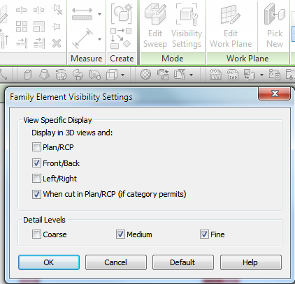
1. It might it’s a family set up to be not displayed in a particular view type. If it were a floor plan, try to find it by changing to another view type, e.g. elevation view, 3D view, or section view. If you can access the edit mode of the family, check the visibility settings selecting its geometry, at Properties Palette on Graphics> Edit Visibility / Graphics Overrides under the section Display in 3D and.
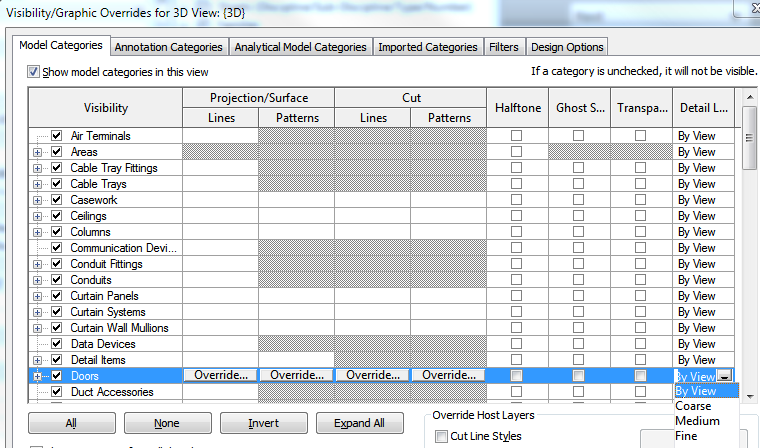
2. It might it’s a family set up to be not displayed in a particular detail level. Change the view to another detail level to find out where the element is. If you can access the edit mode of the family, check the visibility settings selecting its geometry, at Properties Palette on Graphics> Edit Visibility / Graphics Overrides under the section Detail Levels. To rule out that this is the problem, go also to VV (Visibility / Graphics Overrides) on the Model Categories tab, and check that it is not forced the level of detail (Detail Level column) for the category to which the element belongs (it might be the strange case that you have a family configured to not display in the lower level of detail, and that the view in question has forced the family category to show only in low detail level).
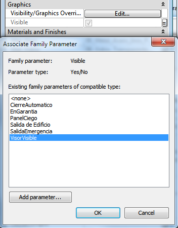
3. It might be because the family has a visibility parameter that is wrongly assigned and it’s not displayed in the project. As in the family editing environment you can always see everything (only changes to a slightly more subdued tone) mistakes can be made on occasion.
4. If it’s a face based family and placed on a non-horizontal plane of the project (e.g. a light switch on a wall), we must consider the representations of the family in different views, will not match between the family editing environment and the project. That is, the view of the reference plane in the family is an elevation in the project, so if you place a symbol on the floor plan of the family, we won’t see it on the floor plan of the project, but in some elevation view.
5. If it’s a mass, it may be turned off, since it is a category not visible by default. Check in Massing & Site> Conceptual Mass> Show Mass Form and Floors. – Si es una masa, puede que esté apagada, puesto que es una categoría no visible por defecto. Comprobarlo en Massing & Site > Conceptual Mass > Show Mass Form and Floors.
6. Something really unlikely, but could happen, is that the element has the color of their lines as the background (usually white) or invisible, and we are in the visual style of Hidden Line. It may be due to changes in viewing through Override Graphics in View or Mange> Settings> Object Styles. The invisible lines may have changed over Linework> Line Style> Invisible Lines. To fix this we need to select the element, and for that we can change the visual style to Shaded either make multiple selections with a capture covering the area where the object is, and use the selection filter.
7. It might it’s an object too small or large due to a family scale. If it’s too small will be lost among other elements, and if large could go undetected until you type ZF (zoom to fit).
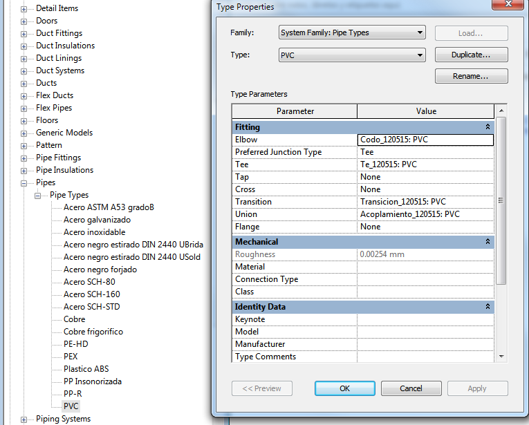
8. With MEP fittings can happen that being loaded in the project they’re not properly assigned with the System Type. It must be corrected on the Project Browser> Families> Pipes> Pipes Types. The same path also for ducts and conduits. The first image shows the dialog box on the 2012 version, and the second one on 2013 version. Families of ducts, pipes and conduits are only displayed on the Project Browser once they’re created, unless it has already been done in the template with which the project began.
9. Another problem with the MEP fittings, though it doesn’t have to do with visualization, is that even being assigned correctly with systems, they don’t work when placing pipes or ducts, keeping the System Type and Classification Undefined and disconnected. The cause is in the project template. We have found that when you start from scratch a template, without relying on Autodesk already configured templates, this error happens. The solution is to copy the model out and paste into a new template without this problem. It would be better, if you didn’t have to do it.
10. As an alternative to previous cases, it may be a family with a selected category that does not match with its use. For example, a fire extinguisher as a generic model instead of Mechanical Equipment do not display correctly in a view of the mechanical discipline.
11. As an alternative to previous one, connectors only work with fittings and terminal equipments, either mechanical, electrical, lighting fixtures, etc. In other words, even though you can place connectors on MEP accesories, they’re useless.
12. If it’s a grid, a level line or a reference line not visible, it might be because it’s restricted to a Scope Box, and at the specific view is not visible. To check, you have to detect another view in which you can see the element and look at Properties> Extents> Scope Box, or locate the Scope Boxes and change the views where is visible under Properties> Extents> Edit Views Visible.
13. The materials editor can also play you a trick if you’re not accustomed to its use. It’s common to save Property Sets of materials to apply them by groups. When duplicating a material with a Property Set assigned, the first thing to do is go to the Appearance tab and change to Independent under Properties (Revit 2012) if you don’t want to change the display the other materials with the same Property Set. With Revit 2013, you know that the Property Sets are equivalent to Assets, and it’s this feature what you should replace or duplicate in order not to affect other associated materials.
14. If you change the material associated to an element and it doesn’t modify its appearance, it can happen that is painted by the Paint tool (PT) at Modify> Geometry> Paint. In this case, the answer is to remove the paint, clicking the drop down menu to access the Remove Paint tool.
15. Another behavior that can drive you crazy is to lose control of how to display an element when changing its material, or its visibility parameters when it’s a family. This is usually because between two or more elements, there is a joined geometry that makes them behave together taking the properties of the first highlighted. There’s no choice but to unjoin geometries to solve it.
1. Puede tratarse de una familia configurada para no visualizarse en un tipo de vista determinada. Cambiar a otro tipo, por ejemplo alzado, vista 3D o sección si se trataba de una planta para tratar de localizarlo. Si podemos acceder al modo de edición de la familia, comprobar su configuración de visibilidad seleccionando su geometría, en la paleta de propiedades Graphics > Edit Visibility / Graphics Overrides en el apartado de Display in 3D and.
2. Puede tratarse de una familia configurada para no visualizarse en un nivel de detalle determinado. Cambiar a otro nivel de detalle para tratar de localizarlo. Si podemos acceder al modo de edición de la familia, comprobar su configuración de visibilidad seleccionando su geometría, en la paleta de propiedades Graphics > Edit Visibility / Graphics Overrides, en el apartado de Detail Levels. Para descartar que este sea el problema, hay que ir también a VV (Visibility / Graphics Overrides) en la pestaña de Model Categories, y fijarse que no esté forzado el nivel de detalle (en la columna Detail Level) para la categoría a la que pertenece el elemento (podría darse el extraño caso de que tengamos una familia configurada para que no se muestre en el nivel de detalle bajo, y que la vista en cuestión tenga forzada la categoría de esa familia para que sólo se muestre en nivel de detalle bajo).
3. Tal vez la familia tenga un parámetro de visibilidad que está erróneamente aplicado y no lo muestra en el proyecto. Como en el entorno de edición de familias siempre se ve todo (sólo cambia a un tono ligeramente más apagado) puede cometerse ese error en alguna ocasión.
4. Si es una familia por cara y en proyecto se coloca sobre un plano no horizontal (por ejemplo una toma de corriente sobre un muro), debemos tener en cuenta que las representaciones de la familia en las vistas, no se corresponderán entre el entorno de edición de la familia y el proyecto. Es decir, la vista del plano de referencia en la familia será un alzado en el proyecto, por lo que si colocamos un símbolo en la planta de la familia, no lo veremos en la planta del proyecto, sino en el alzado.
5. Si es una masa, puede que esté apagada, puesto que es una categoría no visible por defecto. Comprobarlo en Massing & Site > Conceptual Mass > Show Mass Form and Floors.
6. Algo realmente improbable, pero que podría pasar, es que el elemento tenga el color de sus lineas igual que el fondo (generalmente blanco) o sean invisibles, y estemos en el estilo visual de lineas ocultas (Hidden Line). Puede deberse a cambios de visualización a través de Override Graphics in View o en Mange > Settings > Object Styles. Las líneas invisibles podrían haberse cambiado a través de Linework > Line Style > Invisible Lines. Para solucionarlo necesitamos seleccionarlo, y para ello podemos cambiar el estilo visual a Shaded o bien hacer una selección múltiple con una captura que abarque la zona en la que está el objeto, y utilizar el filtro de selección.
7. Quizá, se trate de un objeto demasiado pequeño o grande debido a un error de escala de la familia, y eso es lo que nos impide verlo. Si es muy pequeño quedará perdido entre otros elementos, y si es muy grande, podríamos tenerlo encima sin detectarlo hasta que no hagamos una extensión de la vista.
8. Con los fittings puede pasar que estando cargados en el proyecto no estén debidamente asociados a los System Type. Hay que corregirlo en el Project Browser > Families > Pipes > Pipes Types. Idem para Conductos de Climatización (Ducts) y Tubos Eléctricos (Conduits). La primera imagen muestra el cuadro de diálogo en la versión 2012, y la segunda en la versión 2013. Las familias de Conductos, Tuberías y Tubos sólo se muestran en el Buscador de Proyecto una vez que se crean, salvo que ya se haya hecho en la plantilla con la que se inició el proyecto.
9. Otro problema relacionado con los fittings, aunque no tiene que ver con la visualización, es que incluso estando bien asociados a los Sistemas, no funcionen al trazar tuberías o conductos, quedándose con Undefined el System Type y el System Classification y sin conectar. La causa está en la plantilla del proyecto. Hemos comprobado que cuando se inicia desde cero una plantilla, sin apoyarse en las que Autodesk ya tiene configuradas, se produce este error. La solución es copiar el modelo y pegarlo en una plantilla nueva sin este problema. Mejor que no haya que hacer esto nunca.
10. Como variante de otras, puede tratarse de una familia con una categoría seleccionada que no se corresponda con su uso. Por ejemplo, un extintor como modelo genérico en lugar de Mechanical Equipment no se visualizará correctamente en una vista de la disciplina mecánica.
11. Como variante del anterior, los conectores sólo se ven si la categoría del equipo se corresponde con un terminal o de unión como los fittings, ya sea mecánico, eléctrico, luminaria, etc. Es decir, aunque los conectores se pueden colocar en familias de accesorios, no sirven para nada.
12. Si se trata de un eje o rejilla, un nivel o una linea de referencia no visible, puede deberse a que esté restringida con una Caja de Referencia o Scope Box, y en la vista en cuestión no esté visible. Para hacer la comprobación, hay que detectar otra vista en la que sí veamos el elemento y fijarse en Properties > Extents > Scope Box, o bien localizar las cajas de referencia del proyecto y cambiar las vistas en las que es visible en Properties > Extents > Edit Views Visible.
13. El gestor de materiales puede jugarnos también una mala pasada si no estamos acostumbrados a su uso. Es común guardar conjuntos de propiedades de materiales para aplicárselos a varios. Cuando duplicamos un material que tiene asignado un conjunto de propiedades, lo primero que hay que hacer es ir a la pestaña de Apariencia y cambiarlo a Independiente en Propiedades (Revit 2012) si no queremos que eso altere la visualización del resto de materiales con el mismo conjunto. Con Revit 2013, sabéis que las Property Sets son Assets, y que son estas las que hay que sustituir por otras o duplicarlas para no afectar al resto de materiales asociados.
14. Si nos ocurre que aunque cambiemos el material asociado a un elemento y este no se altera, puede suceder que esté pintado mediante la herramienta Pintura (PT) situada en Modify > Geometry > Paint. En ese caso, la solución es eliminar la pintura desplegando Paint para ver Remove Paint.
15. Otro comportamiento que puede volvernos locos es el de perder el control de visualización de un elemento al cambiarle de material o sus parámetros de visualización si se trata de una familia. Esto suele ser porque entre dos o más elementos hay una unión de geometría que hace que se comporten solidariamente, tomando las propiedades del primero en seleccionarse. No queda más remedio que separar las geometrías para resolverlo.
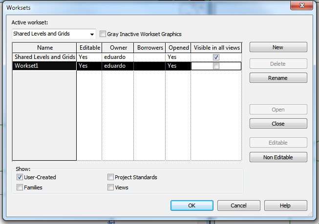
1. Check if theworkset to which the element belongs is visible on Collaborate> Worksets> Visible in all views (box checked). This affects all views and users of the central file.
2. Check if the workset to which the element belongs is open under Collaborate> Worksets> Opened (Yes). This DOES NOT affect all views and users of the central file, only affects local files where is selected.
3. Check if the workset to which the element belongs is visible at VV (Visibility / Graphics Overrides > Worksets)
1. Comprobar que el workset (subproyecto) en el que está el elemento está visible en Collaborate > Worksets > Visible in all views (casilla marcada). Esto afecta a todas las vistas y usuarios del archivo central.
2. Comprobar que el workset (subproyecto) en el que está el elemento está abierto en Collaborate > Worksets > Opened (Yes). Esto NO afecta a todas las vistas y usuarios del archivo central, sólo a cada usuario en su local en el que se selecciona.
3. Comprobar que el workset (supproyecto) en el que está el elemento esté visible en la propia vista en VV (Visibility / Graphics Overrides > Worksets)
1. Check if the link to which the element belongs is loaded on Manage> Manage Project> Manage Links> Revit> Status.
2. Check if the Workset to which the element belongs is open on Manage> Manage Project> Manage Links> Manage Worksets.
3. Check if the Workset to which the element belongs is turned on at the view. Go to VV (Visibility / Graphics Overrides > Revit Links).
4. Check on VV> Revit Links> Display Settings if the visibility settings of the link does not prevent to see the element or category.
5. Make sure you’re linking the right file with the elemento you’re seeking. To do this, you may have to open separate linked files and do some of the above checks.
6. Check if shared coordinates of the linked file to which the element belongs, are the same as the host file. The easiest way is to go to a floor plan view of both files and type RH to display all hidden items. Making a selection of the Survey Point to verify the coordinates, they must be matched.
7. Phase Mapping. It would be really convoluted, but it is possible that between a link file and its host, there is no identical phase relationship, and that makes a phase of a link not visible in a view, although the phase with the same name is turned on in the host file. To see it you should go to the type properties of the selected link.
8. You can want to see annotations from a view of a link within a host file. To do this, go to VV> Revit Links> Display Settings> Basics> By linked view, and choose the appropiate view.
1. Comprobar que el vínculo (link) al que pertenece el elemento está cargado en Manage > Manage Project > Manage Links > Revit >Status.
2. Comprobar que el Workset al que pertenece el elemento esté abierto en Manage > Manage Project > Manage Links > Manage Worksets.
3. Comprobar que el vínculo (link) al que pertenece el elemento está encendido en la vista. Ir a VV (Visibility / Graphics Overrides > Revit Links).
4. Revisar en VV > Revit Links > Display Settings que la configuración de visibilidad del vínculo no impide ver el elemento o categoría.
5. Asegurarse de que el vínculo (link) es al que pertenece el elemento que buscamos. Para ello, tal vez tengamos que abrir por separado los archivos vinculados y hacer algunas de las comprobaciones anteriores.
6. Comprobar que las coordenadas compartidas del vínculo al que pertenece el elemento sean las mismas que las del archivo en el que está enlazado. La forma más sencilla es ir a una vista de planta de ambos archivos y teclear RH para visualizar todos los elementos ocultos. Hacer una selección del Survey Point para comprobar las coordenadas, que deben ser coincidentes.
7. Phase Mapping. Sería realmente enrevesado, pero es posible que entre un vínculo y su anfitrión exista una relación de fases no idéntica, y que haga que una fase de un link no sea visible en una vista aunque en el anfitrión esté encendida la que tiene el mismo nombre. Para verlo hay que ir a las propiedades del tipo con el vínculo seleccionado.
8. Podemos querer ver anotaciones de una vista de un vínculo dentro de un archivo anfitrión. Para ello hay que acceder a VV > Revit Links > Display Settings > Basics > By linked view, y elegir la vista correspondiente.
To the eminent “Revithologists” Carlos Toribio, Nacho Urribarri and Oscar Albarran, for their contributions in some cases.
A los eminentes “revitólogos” Carlos Toribio, Nacho Urribarri y Oscar Albarrán, por sus aportaciones en algunos de los casos.

I’ve got it. Ya lo tengo.

